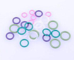
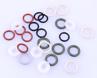
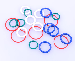
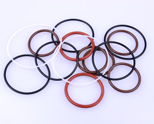
O-Shape"section is called O Ring. It is widely used in Hydraulic and pneumatic transmission system. Avoid leakage of liquid & gas under static condition. In some cases, o ring could be used as dynamic sealing parts when Reciprocating axially and low speed rotary motion. Its structure simple, installation conveniently, low cost, repairing easily, and various materials. It could seal oil, water, gas, and each kind of fluid. Different conditions with different materials.
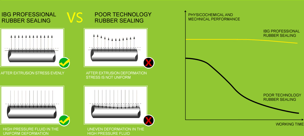
As the sealing principle, o ring is belong to exclusion seals, that basic working principle is happening elastic deformation depending on sealing parts, and causing contact pressure in sealing contact surface, when the contact pressure is greater than the sealing medium pressure, do not leak, otherwise leakage.
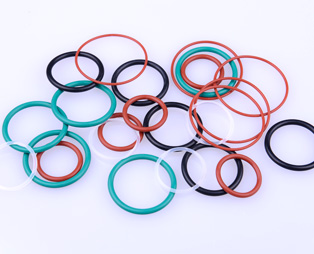

O Ring Size Standard Show:ID*CS
Standard:GB3452.1 SeriesAS568 SeriesJIS B2401 Series
★Note: Non-Standard size could be customized.
IBG Advantage
The reasons that we could cooperate with our customers in a long term: suitable material, innovation strength, strictly quality management and more experience. We have more 20000 molds and large raw material recipe database, could solving each sealing problems.
My company and the customers a solid partnership depends on the achievement of the following aspects: the basic experience material applicability, innovation strength, strict quality management and function integration. Our company has more than 20000 sets of molds with huge database of raw material, processing the sealing problem of seals in various media and various conditions with enough experience.
The procurement division, according to the importance and function of sealing parts, sometimes referred to as C class supplies purchase, in fact the sealing member should belong to a class material. Hydraulic and pneumatic valve seal is the core component technology.
Material Advantage
Cooperation with Dupont, JSR, Dow corning and large raw material recipe database, make our material properties are relatively stable, ensure quality. Rubber formula design ability which make us meet customers demand better.
Product Inspection&Quality Control
Material Inspection:
Take testing for all storage material, and issue the corresponding raw material property report, meanwhile compare with raw material own property report, two reports property value is consistent, then put into storage.
Mold Inspection:
Die Mold development finished or after cleaning, we will check the full size of the mold, ensure quality for each cavity's product.
Product Inspection:
During production, inspectors will check semi-finished products, ensure product process and make the defective rate control in a reasonable range
Quality Control:
Quality Department will check product appearance for each batch.
Quality Department will check product appearance for each batch:
Optional Sorting Machine ensure products appearance, 100% qualified.
Working Condition:0~70Mpa
Speed:Maximum rotational speed up to0.5m/s Maximum reciprocating speed up to2.0m/s
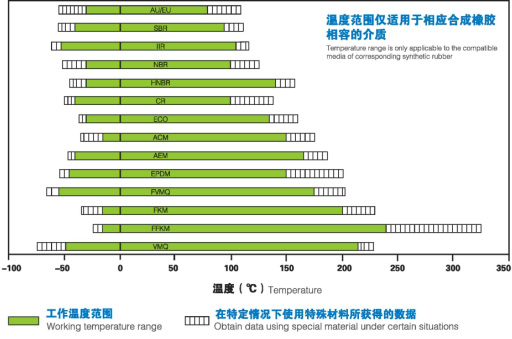
Application Temperature:-60℃~320℃
Working medium:each kind lubricating oil, liquid and gas
Hardness is related with compressive directly. Normal conditions, hardness is higher, high voltage resisting is stronger.
| Hardness ( shores A) | 50±5 | 60±5 | 70±5 | 80±5 | 90±5 |
| Working pressure static seal/Mpa ≤ | 0.5 | 1 | 10 | 20 | 50 |
|
Working pressure static seal Speed≤0.2m/s)/Mpa ≤ |
0.5 | 1 | 8 | 16 | 24 |
According to working condition, choose suitable material.
| Diameter(ID) | Tolerance(±) |
| ≤2 | 0.1 |
| 2.01-10 | 0.13 |
| 10.01-20 | 0.19 |
| 20.01-30 | 0.26 |
| 30.01-40 | 0.34 |
| 40.01-50 | 0.41 |
| 50.01-60 | 0.48 |
| 60.01-70 | 0.55 |
| 70.01-80 | 0.61 |
| 80.01-90 | 0.69 |
| 90.01-100 | 0.76 |
| 100.01-125 | 0.82 |
| 125.01-140 | 0.99 |
| 140.01-155 | 1.09 |
| 155.01-175 | 1.19 |
Diameter tolerance standard table1
| Diameter(ID) | Tolerance(±) |
| 175.01-200 | 1.33 |
| 200.01-250 | 1.49 |
| 250.01-280 | 1.82 |
| 280.01-330 | 2.01 |
| 330.01-360 | 2.33 |
| 360.01-400 | 2.52 |
| 400.01-440 | 2.78 |
| 440.01-470 | 3.05 |
| 470.01-500 | 3.32 |
| 500.01-530 | 3.41 |
| 530.01-560 | 3.6 |
| 560.01-600 | 3.78 |
| 600.01-630 | 4.03 |
| 630.01-650 | 4.22 |
| 650.01-670 | 4.34 |
Diameter tolerance standard table2
| Wire diameter(CS) | Tolerance(±) |
| - 2.00 | 0.08 |
| 2.01 – 3.00 | 0.09 |
| 3.01 – 4.00 | 0.10 |
| 4.01 – 5.00 | 0.12 |
| 5.01 – 7.00 | 0.15 |
| 7.01 – 10.00 | 0.20 |
| 10.01 – 15.00 | 0.25 |
| 15.01 – 25.00 | 0.35 |
| 25.01 – 100.00 | 0.45 |
The wire diameter tolerances standard table
O ring in the groove will be deformation under medium pressure. More pressure, more larger deformation, so sealing effect will be better. If pressure beyond limited value, o ring will be pushed into gap, caused o ring failures. So groove design must be reasonable.
Working pressure higher, gmax allowed smaller. If g beyond range, will cause o ring damaged.
One of index for o ring performace is permanent compression deformation of material. Under pressure, o ring elasticity deformed, pressure bigger, will cause permanent compression deformation. Its formula as follows:
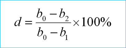
Note: b0-oringinal thickness( section dia.) b1-thick under pressure b2-thickness after release
Normal, in order to avoid permanent compression deformation, max pressure under static seals is about 30%, under dynamic seal is about 20%.
E (%):Compression ratio
T(mm):Compression allowance(T=W-H)
W (mm):O Ring size
H(mm):The depth of the groove
n (%) :The filling rate
G (mm):The width of the groove
Compression Ratio-------------------------------------------------------------------------------------------------------------
Application Range:
8%-30%(dynamic seal:8%-20%;static seal:15%-30%)
Filling Ratio---------------------------------------------------------------------------------------------------------------------
Application Range:
max90%、Value75%
Unit(mm)
| w | Radial dynamic & static | Limited to shaft seal | Radius | |||||
|
Groove depth e1+0.06 |
Groove Width | |||||||
| g0+0.2 |
backup ring g1+0.2 |
backup ring g2+0.2 |
Groove depth e2+0.2 |
Groove depth g+0.2 |
Without backup ring |
With backup ring |
||
| 1.20 | 0.80 | 1.40 | - | - | 0.65 | 1.40 | 0.20 | - |
| 1.25 | 1.00 | 1.80 | - | - | 0.85 | 1.80 | 0.20 | - |
| 1.52 | 1.20 | 1.90 | 2.90 | 3.90 | 1.00 | 2.10 | 0.20 | 0.20 |
| 1.78 | 1.45 | 2.20 | 3.60 | 5.00 | 1.20 | 2.40 | 0.40 | 0.20 |
| 1.80 | 1.45 | 2.20 | 2.60 | 5.00 | 1.20 | 2.40 | 0.40 | 0.20 |
| 1.90 | 1.65 | 2.50 | 3.90 | 5.30 | 1.40 | 2.50 | 0.50 | 0.30 |
| 2.40 | 2.00 | 2.90 | 4.30 | 5.70 | 1.70 | 3.20 | 0.50 | 0.30 |
| 2.62 | 2.25 | 3.10 | 4.50 | 5.90 | 1.90 | 3.60 | 0.60 | 0.30 |
| 3.50 | 3.10 | 4.20 | 5.60 | 7.00 | 2.70 | 4.80 | 1.00 | 0.40 |
| 3.53 | 3.10 | 4.20 | 5.60 | 7.00 | 2.70 | 4.80 | 1.00 | 0.40 |
| 5.33 | 4.70 | 6.20 | 7.90 | 9.60 | 4.30 | 7.10 | 1.20 | 0.40 |
| 5.70 | 5.00 | 6.70 | 8.40 | 10.10 | 4.60 | 7.70 | 1.20 | 0.60 |
| 7.00 | 6.10 | 8.20 | 10.70 | 13.20 | 5.80 | 9.50 | 1.50 | 0.60 |
| 8.40 | 7.50 | 9.70 | 12.20 | 14.70 | 6.90 | 11.70 | 2.00 | 0.60 |
| If you need to have a greater expansion, the width of the groove can be increased by 20% | ||||||||
- Sealing parts with rough edge is usually in the low pressure side.
Description
- Clearance/pressure is too large; hardness/elasticity is too low; groove gap is too small; irregular clearance size; improper size of sealing parts.
Reason
- Reducing clearance size, choosing higher hardness or better elasticity material, reasonable groove design.
Solutions
- Sealing parts become twisting.
Description
- Improper installation, movement speed is too low, material too hard or elasticity too small, improper groove size, rough groove surface.
Reason
- Correct installation, choosing high elasticity material, suitabel groove designation and surface finish, trying to use support ring.
Solutions
- Contacting surface of Sealing parts display permanent deformation.
Description
- Pressure is too large, higher temperature; un-finished sulfuration treatment; material is overexpansion in the chemical medium.
Reason
- Choosing material which is low deformation rate; suitable groove design;confirming materials and medium are compatibility.
Solutions
- The whole or part of sealing parts appear wound.
Description
- The edge of groove is sharp, size is not suitable. Hardness or elasticity is lower; Surface is dirty.
Reason
- Clear sharp edge; design more reasonable groove designation; choose suitable size; choose more elasticity and higher hardness sealing parts.
Solutions
- Sealing parts contacting surface is plane deformation, maybe have crack.
Description
- Unreasonable designation; material deformation, which is caused by heat and chemical medium; or lager pressure
Reason
- Groove designation shoule consider material deformation, which is caused by heat and chemical medium; or lager pressure.
Solutions
- High temperature contacting surface shown radial crack; maybe material change softer, or material become shiny due to high temperature .
Description
- Material could not bear high temperature, or temperature beyond estimated , or temperature change frequently.
Reason
- Choose high temperature resistance material, if possible, try to reduce temperature of sealing surface.
Solutions
- Seal fade also have powder residue on the surface.
Description
- Chemical reactions bring electrolysis, unreasonable groove designation, material and medium is incompatible
Reason
- Choos suitable material with medium, checking groove designation.
Solutions
- The whole or parts of is wear, material wear particle could be found.
Description
- Surface cleaness is worse, more higher temperature, seal surface treatment is notThorough.
Reason
- Using groove cleaness which is suggested, clean wear pats.
Solutions
- The seal surface appear bubbles, pits, scars; pressure material absorption gas in medium, when the pressure is sulienly reduced, the gas absorbed by the material fast escape. Cause sealing epidermal blasting.
Description
- Pressure changed frequently, hardness and elasticity of material too low.
Reason
- Choose higher hardness and elasticity material, reduce decompression speed.
Solutions
- Chemical corrosion could cause each kinds defects, such as crack, small hole or color fading, sometimes, chemical corrosion could be tested by instruments.
Description
- Materials and medium does not match, or higher temperature.
Reason
- Choose more chemical resistant material.
Solutions
- It is difficult to test this flaw, normal form--section size become smaller.
Description
- Improper sulfidizing, hardness too low, or used plasticizer material.
Reason
- Avoid using plasticizer material, assure the sealing parts through correct fluidization process, in order to reduce leakage.
Solutions
- Section of sealing parts have dirty matters.
Description
- The producing environment is damaged, material is corrosion, material is non semiconductor industry grade material.
Reason
- Pay attention to cleaness when producing and packing, controlling environment of deliverying and application.
Solutions